
Industrial equipment
Railway Wheel Welding Machine
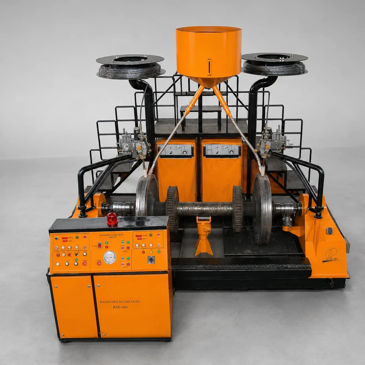
A machine for controlled surfacing and restoration of worn railway wheel surfaces. Steady wheel rotation and precise welding settings help produce a continuous, repeatable deposited layer.
Talk to an engineerFull description
Railway wheel welding machines mechanize the build-up welding and resurfacing of worn wheel surfaces, including the tread and flange. The wheel rotates at a controlled speed while the welding head deposits material in a consistent path. After welding, the wheel can be machined to its specified final profile. Repair must only be undertaken when the wheel material, wear condition, applicable railway maintenance rules, and an approved welding procedure permit it.
What Is a Railway Wheel Welding Machine?
The machine supports and rotates a railway wheel or wheelset while an adjustable torch or welding head deposits metal on the designated surface. The operator or control system sets wheel rotation, wire feed, current, voltage, torch position, and travel or oscillation according to the approved welding procedure specification (WPS). Depending on the fixture, the equipment may also process other circular parts and industrial rollers.
Why Restore Railway Wheels?
Wheel treads and flanges wear under repeated rail contact, curves, braking, and heavy loads. Inspection determines whether reprofiling, approved weld repair, or replacement is appropriate. Build-up welding can recover material for subsequent machining when the applicable engineering and maintenance rules authorize the repair. It is not suitable for every wheel or defect.
How the Welding Cycle Works
- Load the wheel or wheelset with suitable lifting equipment and secure it in the fixture.
- Center the workpiece and check its position and support before rotation.
- Set the welding head height, lateral position, angle, stand-off distance, and any traverse or oscillation.
- Set the approved current, voltage, wire feed, wheel rotation speed, pass overlap, and any required preheat and interpass temperatures.
- Rotate the wheel and deposit material around the selected tread, flange, or other approved area. Apply additional passes or layers as specified.
- Inspect the deposit, follow the specified cooling procedure, and machine or grind the wheel to its required final profile.
Welding Process and Consumables
Submerged arc welding (SAW) may be specified for this application. In SAW, a continuously fed wire forms the weld beneath a layer of flux. The process can support mechanized, high-deposition work, but it is not automatically appropriate for every railway wheel. Process selection depends on the wheel steel, wear location, required deposit thickness and properties, consumables, heat treatment, quality requirements, and approved repair procedure.
Main Components
- A rigid frame and workpiece support designed for the specified wheel or wheelset.
- A rotation drive with motor, gearbox, coupling, and adjustable speed control.
- A fixture for centering and holding a single wheel or supporting a wheelset at suitable points.
- An adjustable welding head or torch with a wire feeder and compatible welding power source.
- Optional flux delivery and recovery equipment when the specified process is SAW.
- An electrical cabinet and, where ordered, PLC and HMI controls.
- Guards, emergency stop, movement limits, and measures against unintended startup; suitable fume extraction and ventilation.
Capabilities and Benefits
Depending on the installed configuration, the machine can provide steady rotation, inverter-based speed adjustment, controlled welding current and voltage, multidirectional torch adjustment, repeatable pass overlap, and manual or automated operation. Data logging and programs for different wheel sizes can be added to a project specification. Actual equipment and capabilities are defined by the ordered configuration.
- More uniform circumferential deposits and repeatable settings than an entirely manual setup.
- Controlled workpiece rotation and easier coverage of the selected welding area.
- Lower operator fatigue during long or repeated passes.
- Potentially higher throughput and less scrapping where repair is permitted and economically justified.
- Possible use for other round components when suitable fixtures and procedures are provided.
Manual and Mechanized Wheel Welding
| Criterion | Manual welding | Mechanized wheel welding |
|---|---|---|
| Travel speed | Depends heavily on the operator | Adjustable and controlled |
| Deposit uniformity | Can vary from pass to pass | More repeatable with correct settings |
| Workpiece rotation | Difficult or requires separate equipment | Integrated, controlled rotation |
| Welding parameters | More dependent on operator control | Set and monitored through the system |
| Operator fatigue | Generally higher | Generally lower |
| Process data | Usually limited | Logging can be added |
| Repeated production | More difficult to maintain consistently | Better suited to repeated cycles |
| Pass overlap | Relies heavily on operator skill | Can be mechanized |
Mechanization does not replace skilled operators, welding engineering, inspection, or an approved repair procedure.
Weld Quality and Inspection
A quality plan should address wheel base material and consumable certificates, preheat and interpass temperature, current and voltage, rotation speed, visual examination, deposit dimensions, and any required nondestructive testing. Inspection may look for cracks, porosity, lack of fusion, and other discontinuities. Hardness and the final machined wheel profile should be checked where required. The repair history should be recorded. Acceptance levels must be set by the responsible welding engineer and quality team for the project.
Heat Control
Railway wheel steels and their heat-affected zones require careful process control. Where the approved WPS requires it, monitor initial temperature, heating rate, interpass temperature, heat input, cooling rate, insulation, and any post-weld heat treatment. Poor heat control may contribute to cracking, unwanted hardness, residual stress, or changes in material properties. Temperature monitoring or preheating equipment can be specified, but the permitted values must come from the approved procedure.
Available Customization
- Fixture design for the specified wheel diameter and width, or for a complete wheelset.
- Welding process and compatible power source selected for the approved procedure.
- Adjustable rotation drive and automatic torch positioning, traverse, or oscillation.
- Preheating and temperature monitoring equipment.
- Flux supply and recovery for a specified SAW configuration.
- PLC/HMI operation, stored programs, parameter logging, and cycle reports.
- Loading and unloading arrangements, guarding, and other safety provisions.
Technical Specifications
The final specifications are established for each order and approved application; no fixed capacity or size is implied by the following overview.
| Item | Specification |
|---|---|
| Machine | Railway Wheel Welding Machine |
| Operation | Semi-automatic or automatic, according to order |
| Welding process | According to the approved project requirements |
| Primary application | Railway wheel surfacing and restoration |
| Wheel diameter | Customizable |
| Maximum workpiece weight | According to the machine design |
| Rotation speed | Adjustable |
| Speed control | Inverter-based, as specified |
| Number of welding heads | According to order |
| Wire feed | Adjustable |
| Torch positioning | Multidirectional, as specified |
| Control | Manual or PLC/HMI, according to order |
| Preheating | Customizable |
| Flux recovery | Available for applicable configurations |
| Welding parameter logging | Customizable |
| Power supply | According to project equipment |
| Safety equipment | According to the project risk assessment |
Choosing the Right Configuration
Before purchase, establish whether the machine will handle an individual wheel or an axle-mounted wheelset. Provide wheel diameter, width, weight, axle dimensions, and the exact tread or flange area to be welded. The approved welding process and consumables, required throughput, automation level, and available floor space also affect the design. Heavy-part handling, heat, welding fumes, electrical equipment, and operator access must be considered in the project safety assessment.
Maintenance and Service
Routine checks should cover the motor and gearbox, lubricant, rollers and bearings, fixtures, power cables and welding connections, welding head and wire feeder, flux equipment where installed, instruments and calibration, inverter, emergency stop, ventilation, electrical cabinet, grounding, and PLC backups. Inspection intervals depend on operating hours, conditions, and the equipment manufacturer’s instructions. Keep maintenance and repair records.
Information Needed for an Order
- Wheel or wheelset drawings, minimum and maximum diameter, width, weight, and axle dimensions.
- Exact weld location, wheel material, and the approved welding process and consumables.
- Required rotation speed, production volume per shift, and automation level.
- Requirements for preheating, process records, material handling, and available installation space.
Summary
Controlled wheel rotation combined with adjustable welding settings can make approved wheel surfacing more consistent and repeatable. The repair method, parameters, inspection, and final profile must follow the applicable wheel material requirements, WPS, and railway maintenance rules.
Comments (0)
No comments yet.
Leave a comment
Comments and replies appear after moderator review.