
Industrial equipment
Manual-Adjustment Welding Rotator
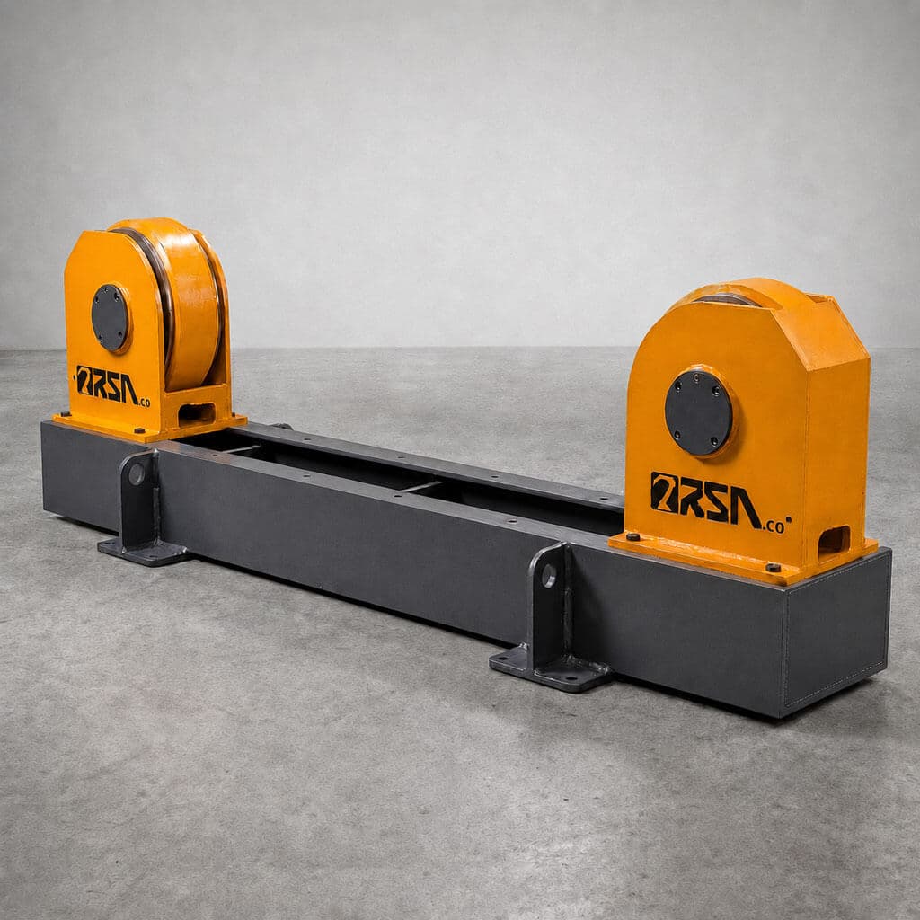
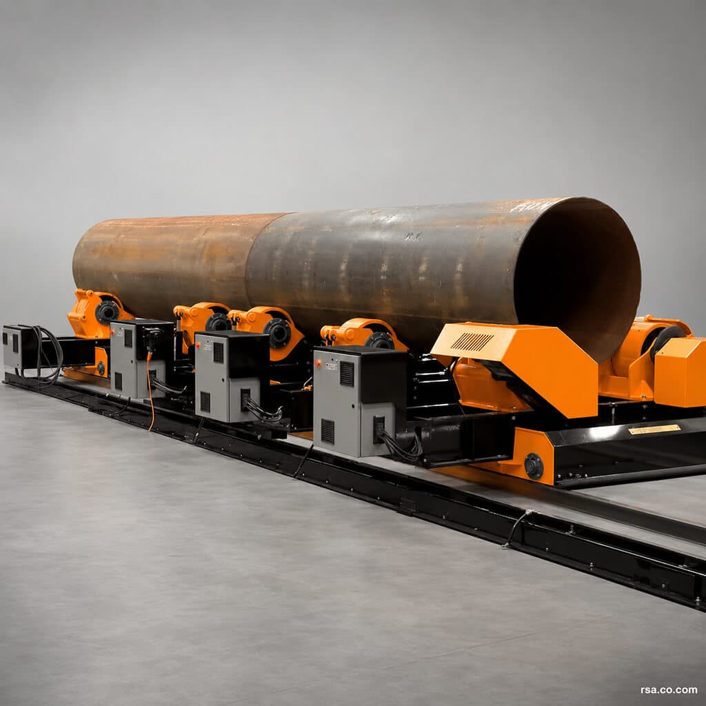
A welding rotator with manually adjustable roller spacing for supporting and turning cylindrical vessels, pipes, and similar workpieces. A drive unit and an idler unit provide controlled rotation within the model’s rated load and diameter range.
Talk to an engineerFull description
A manual-adjustment welding rotator supports and turns vessels, pipes, and other cylindrical workpieces at a controlled speed. The distance between its rollers is set manually to suit the workpiece diameter, allowing one machine to handle several sizes within its designed load and diameter range. Such equipment is also called a conventional or adjustable welding rotator, or tank turning rolls, and is used in welding, assembly, and some finishing operations.
Features
- Controlled turning and positioning for cylindrical parts of different rated weights in vessel, refinery, petrochemical, power, and pipe fabrication.
- Ductile-iron wheels with wear-resistant polyurethane coating in medium-capacity configurations; hardened steel rollers in certain very heavy models.
- Coordinated drive assemblies for consistent movement.
- Adjustable rotation speed through a drive system.
- Roller-spacing adjustment using a lead screw or, where specified, a hydraulic system.
- Wired remote control with a cable of 6 metres or more according to configuration.
Technical Specifications
The following model values reproduce the Persian product specifications. Workpiece load, diameter, and rotation speed must be checked against the drawing and actual machine configuration.
| Model | Load capacity | Rotation speed | Roller surface | Diameter column 1 | Diameter column 2 | T.P. |
|---|---|---|---|---|---|---|
| RBM20 | 20,000 kg | 14–60 cm/min | PU | Ø4,500 mm | Ø300 mm | 2 tonnes |
| RBM40 | 40,000 kg | 12–60 cm/min | PU | Ø6,000 mm | Ø400 mm | 5 tonnes |
| RBM70 | 70,000 kg | 12–60 cm/min | PU | Ø7,000 mm | Ø500 mm | 8 tonnes |
| RBM100 | 100,000 kg | 12–60 cm/min | PU | Ø800 mm | Ø500 mm | 11 tonnes |
Both diameter columns are labeled “D1” in the Persian source, and its first diameter value for RBM100 is Ø800 mm. Confirm the column meanings and that value against the manufacturer’s current technical drawing before selecting a model.
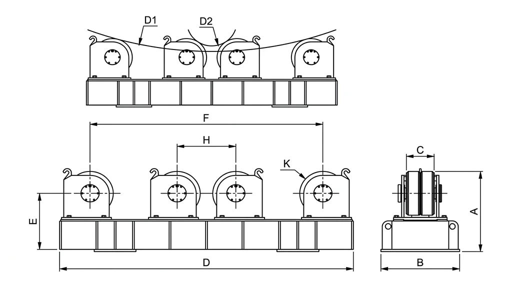
Dimensions
| Model | A (mm) | B (mm) | C (mm) | D (mm) | E (mm) | F (mm) | H (mm) | K (mm) |
|---|---|---|---|---|---|---|---|---|
| RBM20 | 630 | 600 | 150 | 2,000 | 450 | 1,540 | 450 | Ø360 |
| RBM40 | 630 | 630 | 200 | 2,400 | 450 | 1,930 | 450 | Ø360 |
| RBM70 | 700 | 680 | 240 | 2,530 | 510 | 2,000 | 500 | Ø400 |
| RBM100 | 890 | 730 | 280 | 3,000 | 640 | 2,300 | 630 | Ø500 |
What Is a Manual-Adjustment Welding Rotator?
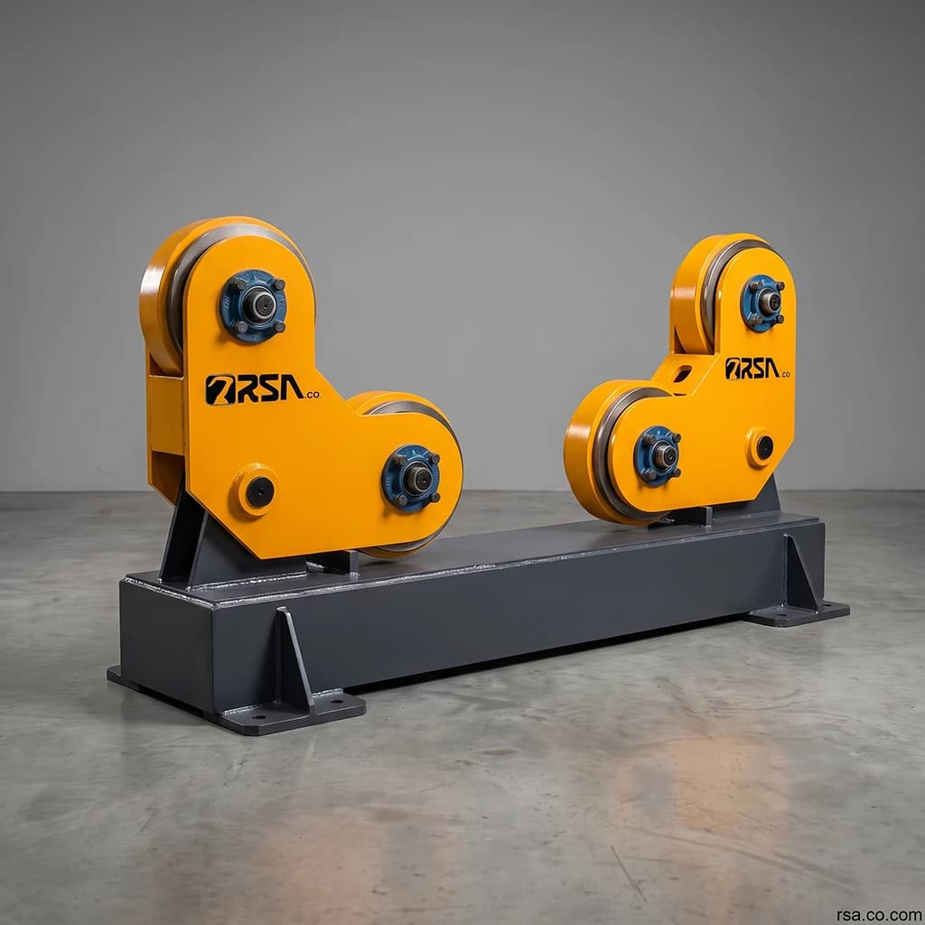
A welding rotator combines rollers and a drive so a cylindrical workpiece can turn about its longitudinal axis. In a typical set, a drive unit supplies rotation and an idler supports the remaining weight. Before operation, the operator changes the roller positions for the workpiece diameter, using a screw, lead screw, or another mechanical adjustment provided by the model. The workpiece must remain within the machine’s rated capacity and diameter range.
How It Works
First, set the roller spacing for the external diameter of the vessel. Place the workpiece on the drive and idler rollers using appropriate lifting equipment. The motor and transmission turn the drive rollers; friction at the contact surfaces rotates the vessel. Controlled rotation presents successive parts of the circumference for welding, assembly, or another approved operation.
Manual Adjustment Versus Self-Alignment
On a manual-adjustment rotator, the operator resets roller spacing when the diameter changes. On a self-aligning model, the roller mechanism adapts to the diameter as the workpiece is loaded. Self-aligning equipment may save setup time where diameters change frequently, while the manual-adjustment design is simpler and may suit production with a stable or limited diameter range.
Applications
- Circumferential welding of vessels and cylindrical pipes.
- Assembly of cylindrical shells and parts.
- Pressure and storage vessel fabrication.
- Tankers, boilers, and industrial pipe production.
- Oil, gas, petrochemical, chemical, and power-plant equipment.
- Shipbuilding and other cylindrical steel structures.
- Some grinding, finishing, coating, and surface-preparation work.
- Integration with welding automation and column-and-boom manipulators.
Check the specific model’s technical limits before using it for any application.
Why Adjust Roller Spacing?
Changing the center-to-center distance between rollers allows the machine to support different workpiece diameters. Some models use a lead screw for relatively continuous positioning; others secure the roller groups at defined positions on the frame. The selected adjustment method depends on the equipment design and project requirements.
Main Components
Drive unit
The drive rotator generates rotation through an electric motor, gearbox, transmission, and powered rollers.
Idler unit
The idler rotator supports the workpiece and helps keep it stable during rotation.
Rollers and spacing mechanism
Rollers contact the vessel surface. Steel, rubber, or polyurethane-contact designs may be selected according to load and surface conditions. The spacing mechanism sets the roller positions for the diameter.
Drive and controls
Motorized systems use a motor and gearbox, with a variable-frequency drive (VFD) available in some configurations for rotation-speed control.
Circumferential Welding and Column-and-Boom Integration
Instead of continually moving the welding operator or head around a large vessel, the rotator turns the joint past a suitable torch position. The system may work with manual, semi-automatic, or automatic welding equipment. When paired with a welding column and boom, the rotator turns the vessel while the manipulator holds the welding head in position. Their movement and process parameters must be coordinated.
Choosing a Manual-Adjustment Rotator
Rated load and distribution
The maximum workpiece weight must remain within the equipment rating. Assess how the load is divided between the drive and idler units.
Diameter range and vessel length
Every model has a defined minimum and maximum diameter. Manual adjustment does not make that range unlimited. Long vessels may need additional idler supports.
Rotation speed and roller material
Select surface speed for welding, assembly, or finishing. Choose roller material for the load, workpiece surface, and operating environment.
Motor and gearbox
Drive power and torque should match the load and duty. Consult the specific model datasheet.
Roller Alignment and Axial Drift
Setting roller spacing is only part of installation. Correct alignment between drive and idler is also important. Misalignment can cause a vessel to move gradually along its axis during rotation, known as drift or creep. Install and align the units according to the manufacturer’s instructions.
Who Uses This Equipment?
Manual-adjustment rotators serve industrial vessel and pressure-vessel builders, tank and storage-vessel manufacturers, oil and gas, petrochemical and chemical plants, boiler and pipe fabricators, shipbuilders, energy companies, and process-equipment workshops.
Difference from a Fit-Up Rotator
A manual-adjustment rotator primarily supports and turns one cylindrical workpiece. A fit-up rotator also helps position and align two or more shell sections before welding, sometimes with hydraulic adjustment. Their purposes and structures are therefore different.
Benefits
- Controlled rotation of cylindrical workpieces.
- Adjustment for several diameters within the model’s specified range.
- Better access around the vessel circumference.
- Support for circumferential welding and related assembly or finishing tasks.
- Possible integration with welding automation.
- Less need for the operator or welding tool to move continually around the workpiece.
Ordering and Pricing
Provide maximum vessel weight, minimum and maximum diameters, length, process, required rotation speed, preferred roller material, operating environment, and the number of drive and idler units needed. These details allow the capacity and arrangement to be selected for the project.
Price varies with load rating, diameter range, drive motor and gearbox, roller material, speed-control system, frame dimensions, and support-unit count. A technical quotation requires the workpiece and operating specifications.
Frequently Asked Questions
What is a manual-adjustment welding rotator?
It supports and turns vessels, pipes, and cylindrical parts while an operator sets roller spacing for the workpiece diameter.
What other English names are used?
Conventional welding rotator, adjustable welding rotator, tank turning rolls, and, for some models, lead-screw adjustable turning rolls.
How does it differ from a self-aligning model?
The operator adjusts roller positions on a manual model; a self-aligning mechanism responds to a new workpiece diameter when loaded.
What is it used for?
Turning cylindrical parts during welding, assembly, vessel fabrication, and some finishing or coating processes.
Does one unit suit every diameter?
No. Every unit has specified diameter and load limits.
What information is needed for an order?
Workpiece weight, diameter range, vessel length, application, and required rotation speed are the main inputs.
Can it be used with automatic welding?
Yes, if the drive and controls are designed to work with the welding system and any column-and-boom equipment.
Summary
The manual-adjustment welding rotator supports and turns cylindrical vessels and pipes. Its defining feature is adjustable roller spacing for different diameters within the machine’s technical limits. Select a model using actual load, diameter, length, surface speed, roller material, and drive requirements.
Comments (0)
No comments yet.
Leave a comment
Comments and replies appear after moderator review.