
Industrial equipment
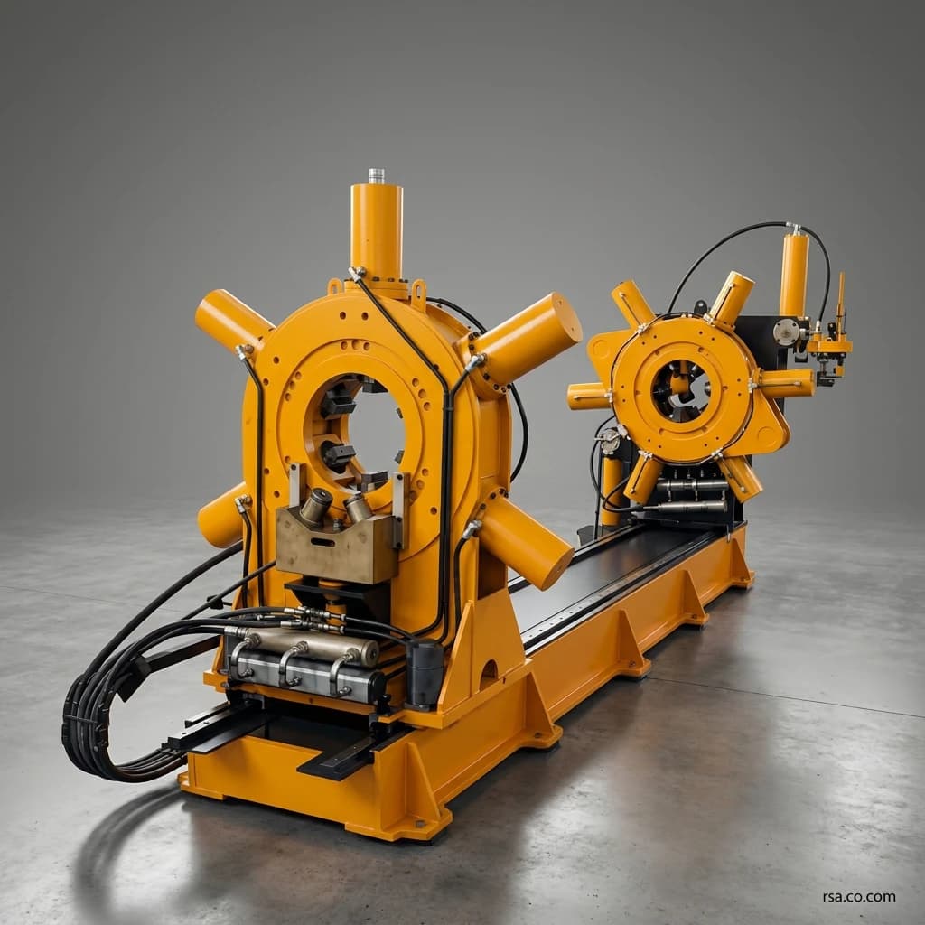
RTO 75 High-Torque Stroking Machine
The RTO 75 is an industrial hydraulic bucking unit for controlled makeup and breakout of heavy threaded connections in drilling and well equipment. It applies up to 75,000 N·m and records torque, force and time for each operation.
Talk to an engineerFull description
The RTO 75 high-torque stroking machine is an industrial hydraulic system for controlled assembly and disassembly of heavy threaded connections. Also known as a bucking unit or makeup/breakout machine, it is used in the manufacture, repair, servicing and quality control of drilling tools, downhole equipment, wellhead equipment and well-completion assemblies.
The machine applies up to 75,000 N·m of torque. Under ideal conditions, that is roughly equivalent to 7.6 tonne-force acting at the end of a one-metre lever. Applying this torque manually or with general-purpose equipment makes accurate torque control, alignment and connection records difficult.
A fixed head, traveling head, hydraulic jaws, spinner, separate hydraulic circuits and PLC control coordinate makeup and breakout. The system records torque, force, time, thread details and connection identity and provides reports and graphs to the operator.
Structure, Operation and Technical Specifications
What Is a High-Torque Stroking Machine?
It applies controlled torque to threaded connections. The fixed and traveling heads hold opposite sides of the workpiece; hydraulic jaws grip them while the torque mechanism turns one component relative to the other. Unlike a hydraulic wrench that applies torque at one point, the integrated station also provides:
Secure holding of both sides of the connection
Alignment and controlled approach of the components
Fast initial thread engagement
Precisely controlled final torque
Breakout of tight or heavy connections
Measurement and logging of process parameters
Quality-control reports for each connection
RTO 75 Operating Sequence
The exact sequence depends on the connection and assembly procedure. A typical sequence is:
Enter workpiece and thread data and the target torque
Position the traveling head for the assembly length
Load the components onto the support rests
Use the hydraulic rests for initial alignment
Clamp both sides with the hydraulic jaws
Bring the components together under controlled axial force
Use the spinner to engage the thread at higher speed
Apply final torque with the main cylinders
Record torque, force and time throughout the operation
Stop at target torque and generate a final report
Breakout follows a corresponding sequence in the opposite direction, with controlled torque applied to release the connection.
Makeup and Breakout
Makeup means tightening a threaded connection to its specified torque. Breakout means loosening it. The breakout torque may differ from makeup torque because of friction, corrosion, deposits, deformation, operating temperature or time in service. RTO 75 supports both directions and records the process.
Fixed Head
The fixed head holds one side of the connection and transfers torque reaction to the main frame. It has six hydraulic holding jaws, controlled clamping pressure, resistance to torsional loads and an initial-makeup spinner. Jaw geometry can be adapted to the part. Jaw material and pressure must prevent slipping without unnecessary surface damage; custom jaws or replaceable inserts may be considered for delicate, coated or special-alloy parts.
Traveling Head
The traveling head holds the other side and moves along the machine axis. It adjusts for different assembly lengths, maintains alignment, provides controlled longitudinal movement and axial force, and follows thread advance during makeup. Proper alignment helps avoid cross-threading, side loads and damage before final torque is applied.
Traveling-Head Drive
The head moves on ground guide rails. A hydraulic motor and rack-and-pinion mechanism provide longitudinal travel. This arrangement supports smooth positioning and controlled stops under industrial loads. Maximum axial travel is 4,000 mm.
Hydraulic Jaws
Twelve hydraulic cylinders operate the holding jaws. Clamping pressure must match part diameter, material, wall thickness, surface condition, applied torque, gripping geometry and susceptibility to jaw marks. Excessive force can damage thin or sensitive parts; insufficient force can allow slipping. The jaw circuit is therefore controlled and measured independently.
Spinner
The spinner handles the initial, lower-torque part of makeup or breakout at higher speed. Its maximum torque is 2,000 N·m and its speed is 10 rpm. Once connection resistance rises, the main torque system takes over. This division can reduce nonproductive cycle time.
Main Torque System
Two parallel hydraulic cylinders generate the main torque. Their linear force is converted to rotation by the machine mechanism. The circuit uses a 22 kW three-phase motor, vane pump, 80 L/min flow, design pressure up to 200 bar, two torque cylinders rated up to 125 kN each, a proportional pressure-control valve, a pressure sensor and a flow divider. Pressure is raised gradually; calibrated pressure, cylinder force and mechanism geometry are used to calculate and record torque.
Main Rotation Speed
The main system operates at approximately 1 rpm for controlled final tightening. The 10 rpm spinner provides faster initial thread engagement, while the slower main system provides higher torque and closer control near the target.
Axial Force
The machine can apply up to 10,000 N of axial force to bring the components together and follow thread advance during makeup. Set this force according to the connection and thread manufacturer’s procedure; an unsuitable force can affect engagement, friction and the final assembly.
Hydraulic Support Rests
Two hydraulic rests support and initially center long or heavy parts. They carry weight, reduce jaw loading, align the axes, assist loading and unloading, limit sagging and improve thread entry. Their position and design may be adapted to project geometry.
Heavy Steel Frame
The main frame uses fabricated steel plate girders at least 20 mm thick. It carries equipment and workpiece weight, jaw and axial forces, and torque reaction. Design considerations include torsion, allowable deflection, rail alignment, start/stop forces, safety factors and foundation fixing. Frame stiffness contributes to head alignment and torque-measurement accuracy.
RTO 75 Hydraulic System
Separate hydraulic circuits control torque, jaws, longitudinal travel and cooling, allowing each function to be managed without unwanted interaction.
Torque Circuit
22 kW three-phase motor
Vane pump; 80 L/min
Design pressure up to 200 bar
Jaw Circuit
22 kW three-phase motor
Vane pump; 100 L/min
Design pressure up to 200 bar
Travel and Spinner Circuit
4 kW motor
Gear pump; 12 L/min
Operating pressure 150 bar
Cooling Circuit
1.5 kW motor
Gear pump; 36 L/min
Design pressure up to 100 bar
Oil Reservoir and Cooling
The 900 L hydraulic reservoir includes an oil-level indicator, thermometer, filtration system, service connections and a return path for cooled oil. An oil-to-air heat exchanger is controlled by oil temperature and a thermostat. Temperature control helps maintain viscosity, valve stability, efficiency and hydraulic-component life.
Operating Pressure
The declared nominal operating pressure is 150 bar. The torque and jaw power circuits are designed for up to 200 bar, while the cooling circuit is designed for up to 100 bar. These ratings are circuit-specific; they should not be treated as one operating pressure for the entire machine.
PLC Control and Touchscreen
An LS-brand PLC and 10-inch HMI allow parameter entry, machine-status monitoring, manual operation, semi-automatic operation and programmable sequences. Individual actuators can be controlled for setup and service. The screen can display live torque, circuit and jaw pressure, elapsed time, oil temperature, jaw and head status, current step, target torque, alarms and torque-versus-time graphs.
Sensors and Interlocks
Sensors include torque- and jaw-circuit pressure sensors, oil-temperature sensing, head-position microswitches, actuator-state detection and end-of-travel limits. Their data support process control and safety interlocks that prevent operation in unsuitable conditions.
Process Records and Reports
For each operation, the software can store live and peak torque, applied force, start and end time, process duration, workpiece identity, connection serial number, thread details, operator ID, target torque, final result, torque–time graph and alarms. These records make each connection traceable against its assembly procedure.
RTO 75 Technical Specifications
Specification | Value |
|---|---|
Model | RTO 75 |
Machine type | High-torque stroking machine |
Maximum main torque | 75,000 N·m |
Maximum spinner torque | 2,000 N·m |
Main rotation speed | 1 rpm |
Spinner speed | 10 rpm |
Workpiece diameter | 80–360 mm |
Maximum axial travel | 4,000 mm |
Maximum axial force | 10,000 N |
Nominal operating pressure | 150 bar |
Maximum design pressure of selected circuits | 200 bar |
Jaw cylinders | 12 |
Maximum force per jaw cylinder | 140 kN |
Torque cylinders | 2 |
Maximum force per torque cylinder | 125 kN |
Oil reservoir | 900 L |
Control | PLC and HMI |
PLC brand | LS |
Display | 10 inches |
Approximate dimensions | 6,000 × 2,300 × 1,600 mm |
Approximate weight | 7,500 kg |
Cooling | Oil-to-air heat exchanger |
Operating modes | Manual, semi-automatic and programmable sequence |
Warranty | One year |
Final figures should be checked against the production drawings, hydraulic circuit and delivered machine datasheet before publication or procurement.
Applications and Benefits
Drilling Tools
Threaded drilling tools must be assembled to the manufacturer’s specified torque. Under-tightening can allow a connection to loosen; excessive torque may damage threads or the tool body. Subject to diameter, length, weight, thread type and torque requirements, RTO 75 can assemble or disassemble drill collars, subs and adapters, directional tools, downhole motor assemblies, fishing tools, bottom-hole assembly components and other high-torque connections.
Downhole Equipment
Downhole equipment operates under pressure, temperature, vibration and mechanical loads, so assembly quality matters. Potential work includes downhole tools, measurement and flow-control devices, drilling-motor parts, packers, completion tools and well-service assemblies.
Wellhead and Completion Equipment
With suitable jaws and fixtures, the machine may handle some large, heavy wellhead connections after their diameter, gripping shape and torque are checked. Completion tools may contain several threaded parts; a record of each connection’s torque supports quality control and assembly traceability.
Oil and Gas Service Workshops
A service shop can use one station for breakout, tool holding, axial positioning, initial makeup, final torque, result logging and delivery reports after inspection or component replacement.
Industrial Equipment Manufacturers
The machine can also support final assembly and quality control in factories that manufacture drilling and downhole equipment.
Faster Makeup and Breakout
Heavy threaded joints need rapid rotation to bring the threads together and high torque near the end. Using only a slow high-torque mechanism increases cycle time. RTO 75 uses its spinner for the first stage and main cylinders for the second.
More Accurate Torque
Instead of relying only on a gauge reading or operator judgment, the machine measures circuit pressure and controls torque through its calibration. Actual and target torque can then be compared and the result recorded.
Connection Traceability
Part number, thread type, target and final torque, time and outcome can be logged for quality control, internal inspection, production records, failure investigation, assembly verification, comparison between connections and customer handover.
Lower Risk of Thread Damage
Misalignment, cross-threading, unsuitable axial force and uncontrolled torque can damage threads. The traveling head, hydraulic rests and axial-force control help align the parts before final torque, while controlled speed and pressure reduce sudden load increases.
Operator Safety
Applying very high torque with improvised levers, chains or cranes can expose operators to slipping parts, released tools and equipment failure. Hydraulic jaws, remote panel operation, guards, emergency stop, interlocks and relief valves reduce these risks. Safe use still requires capacity limits, training, jaw inspection, correct loading and a site-specific risk assessment.
Repeatability and Industrial Duty
Programmable sequences can coordinate clamping, spinning, torque increase and target-torque stop, reducing variation between operators. Independent circuits, a 900 L reservoir, filtration and oil-to-air cooling support repeated industrial cycles. Actual continuous-duty capacity must be defined for each project by cycles per hour, torque-on time, ambient and oil-temperature limits, any required rest period and hydraulic-oil grade.
Comparison with Other Methods and Machines
RTO 75 Versus a Hydraulic Wrench
Criterion | Hydraulic wrench | RTO 75 |
|---|---|---|
Workpiece holding | Separate fixtures or equipment | Integrated hydraulic jaws |
Connection alignment | Depends on setup | Fixed head, traveling head and rests |
Initial thread engagement | Usually separate | Integrated spinner |
Axial force | Limited or separate equipment | Up to 10,000 N |
Torque data | Depends on model | Torque, force and time records |
Connection traceability | Usually limited | Connection identity records |
Long workpieces | Additional equipment often needed | Up to 4,000 mm axial travel |
Automation | Limited | PLC, HMI and programmable sequence |
Repeated work | More operator intervention | Designed for industrial cycles |
A hydraulic wrench is suitable for many field repairs and installed connections. An integrated stroking machine becomes more useful when holding, alignment, initial engagement, data recording and repeatability are also required.
Stroking Versus Fully Rotational Machines
A stroking machine generally creates main torque through limited-angle cylinder strokes, which may repeat to continue turning. This suits heavy connections requiring high torque. In a fully rotational machine, a head turns continuously and may better suit certain tubular or premium-thread connections where turns or torque–angle records matter.
Criterion | Stroking machine | Fully rotational machine |
|---|---|---|
Main motion | Limited-angle, high-force strokes | Continuous rotation |
Typical use | Drilling tools and heavy joints | Tubular connections needing continuous rotation |
High torque | Well suited | Depends on design |
Turn-count control | More limited | Better suited |
Initial spinner | Can be used | May be integrated into drive |
Structure | Torque cylinders and holding head | Rotating head and power transmission |
Choose between these designs according to thread type, required turns, control graph, diameter and connection torque.
Position Among International Products
International machines from Forum, NOV, Weatherford and EnerQuip span different torque and diameter ranges. Maximum torque alone is not a valid comparison; the actual connection requirements matter.
Feature | RTO 75 | Common international approach |
|---|---|---|
Fixed and traveling heads | Included | Common |
Hydraulic system | Included | Common |
Nominal operating pressure | 150 bar | Varies by model |
Spinner | 2,000 N·m | Standard or optional on some models |
Torque graph | Torque–time | Torque–time or torque–turn |
Connection identity record | Included | Common on advanced systems |
PLC and HMI | Included | Common on newer models |
Programmable sequence | Included | Depends on automation level |
Axial travel | Up to 4,000 mm | Depends on frame length |
Diameter range | 80–360 mm | Depends on model |
Customization | Available to order | Often available |
Local support | Domestic manufacturer | Depends on representation and site |
Customer-Specific Design
Machine dimensions, jaw type, tool length, shop space and production process can be adapted to a customer project. Separate hydraulic circuits allow more specific control of torque, jaws, travel and cooling; the 4,000 mm travel supports relatively long assemblies. Process records include more than the final torque, and controlled axial force improves thread engagement.
Domestic Manufacturing and Service
Local production can simplify direct contact with designers, technical service, jaw changes, software changes and custom spare parts. This is valuable where quick engineering support and local customization matter; it is not a claim that the machine outperforms every imported alternative.
Possible Custom Options
Torque–angle or torque–turn recording: The current configuration records torque–time. An encoder and torque–turn record may be considered when acceptance depends on angle, turn count or shoulder torque.
Open-top head: Where heavy tools must be loaded vertically by crane, an open-top head can be evaluated.
Non-marking jaws: Special inserts can reduce marks and stress concentration on coated, machined or corrosion-resistant parts.
Calibration certificate: A certificate stating validity, method and measurement uncertainty can support traceability and customer confidence.
Management-system integration: An optional interface can receive work orders, send reports to a server, store data centrally, connect to SCADA, capture serial numbers by barcode or QR code, and manage user access.
Machine Safety
RTO 75 uses hydraulic relief valves, software pressure and torque limits, mechanical end stops, position switches, emergency stop, hardware safety locks, a polycarbonate guard, jaw-to-torque interlocks, oil-temperature monitoring, overpressure alarms and fault stops to address hazards from hydraulic pressure, moving parts and high torque. Main torque should be enabled only when the jaws, head position and protective systems meet the required conditions.
Torque Hazard Zone
Substantial energy can be stored in the workpiece, jaws and frame during torque application. Operators must stay outside potential paths of part movement, sudden release or equipment failure. The work area needs warning signs, operating procedures and controlled access.
Design Standards
The design takes account of ISO 12100:2010 principles for machinery risk assessment and risk reduction and ISO 4413:2010 general and safety requirements for hydraulic fluid-power systems and components.
RTO 75 Maintenance
Preventive maintenance is essential to preserve accuracy, safety and service life.
Daily Checks
Hydraulic-oil level
Leaks at hoses and fittings
Jaw condition and clean jaw contact surfaces
Emergency-stop function
Fault messages
Unusual pump noise
Periodic Checks
Filter condition and oil operating temperature
Rails and rack-and-pinion drive
Structural fasteners and jaw wear
Relief valves and pressure sensors
Cooling system
Cable and hose carrier condition
Calibration
Calibrate the torque-measurement system at intervals set by cycle count, use, customer requirements and the quality plan. Recalibration is needed after torque-circuit repair, pressure-sensor replacement or changes to mechanical parts that affect torque calculation.
Selection and Ordering Guide
Supply the engineering team with the following information to select or design a suitable configuration:
Required information | Why it matters |
|---|---|
Minimum and maximum part diameter | Jaw and passage design |
Minimum and maximum part length | Travel and frame length |
Part weight | Support rests and loading equipment |
Maximum makeup torque | Torque-system selection |
Maximum breakout torque | Actual machine capacity |
Thread type and standard | Control method |
Surface sensitivity | Jaw material |
Required axial force | Traveling-head design |
Daily cycle count | Hydraulic and cooling design |
Loading method | Head and support arrangement |
Required report | Software design |
Environmental conditions | Components and protection |
Supply voltage and frequency | Electrical cabinet and motor design |
Why Specify Makeup and Breakout Torque Separately?
A connection may require more torque to break out than to make up. A machine sized only for makeup could lack breakout capacity. State the maximum expected values for both operations when ordering.
Why Choose RSA RTO 75?
RSA designed RTO 75 for users who need high torque, accurate component alignment and documented connection assembly. Key features include:
Up to 75,000 N·m main torque
80–360 mm standard part-diameter range
2,000 N·m spinner torque
Up to 4,000 mm axial travel
Proportional-valve torque control
Process data and torque–time graphs
PLC and 10-inch touchscreen
Manual, semi-automatic and programmable modes
Independent jaw and torque circuits
Oil cooling and filtration
Custom jaws and modules
Direct access to the manufacturer’s technical service
One-year warranty
The machine can be further developed to match customer parts, processes and quality-control systems.
Frequently Asked Questions
What does a high-torque stroking machine do?
It makes up and breaks out heavy threaded connections to a specified torque while holding and aligning parts and recording process data.
What is the maximum RTO 75 torque?
The maximum main torque is 75,000 N·m.
Which part diameters does it accept?
The stated standard range is 80–360 mm. Other sizes require assessment of custom jaws or a custom machine.
How does the spinner differ from the main system?
The spinner engages threads faster at lower torque. The slower main system applies much higher final torque.
Can it also break out connections?
Yes. It is designed for both makeup and breakout.
Is each connection torque recorded?
Yes. The controller can record torque, force, time and connection identity and provide a torque–time graph.
Can it stop at the target torque?
In semi-automatic or programmable mode, the controller can stop according to the target torque and configured sequence.
Can it record a part serial number?
Connection identity and thread details can be stored in the report. Barcode or QR-code capture may be considered as an extension.
Are the jaws replaceable?
Yes. Replaceable jaws can be designed for the part diameter, geometry and material.
Are non-marking jaws possible?
Special jaws or inserts can be evaluated for sensitive surfaces, coatings or materials.
What is the operating pressure?
Nominal operating pressure is 150 bar. Some power circuits are designed for up to 200 bar.
Can it work in harsh environments?
It is intended for heavy industrial work. Exact ambient temperature, humidity, dust and area classification must be specified in the project datasheet.
What determines the price?
Torque capacity, diameter range, frame length, jaws, controls, data logging, loading equipment, safety requirements and custom options determine the quoted configuration.
What information is needed for a technical proposal?
Send part drawings, diameter, length, weight, thread type, makeup and breakout torque, axial-force requirement, cycle count and reporting requirements.
Summary
The RTO 75 is an integrated station for controlled makeup and breakout of heavy threaded connections. Hydraulic jaws, fixed and traveling heads, a spinner, torque cylinders, PLC control and data recording combine holding, alignment, assembly and torque verification in one machine.
Its 75,000 N·m maximum torque, 80–360 mm diameter range, 4,000 mm axial travel and torque–time logging make it applicable to drilling tools, wellhead and downhole equipment, and completion assemblies when their individual requirements fall within the machine’s capabilities.
The system can reduce reliance on manual methods, heavy-tool handling risks, operator variation and gaps in connection records. Modular jaws, sensors, software and external-system interfaces can be developed for project needs. Send diameter, length, weight, thread type, makeup and breakout torque and expected cycle count to RSA for a technical proposal and quotation.
Comments (0)
No comments yet.
Leave a comment
Comments and replies appear after moderator review.