
Industrial equipment
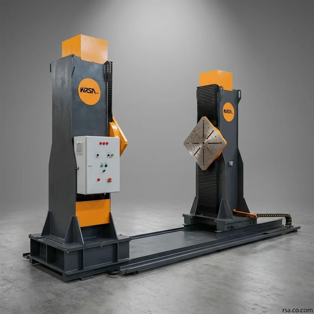
Headstock-Tailstock Welding Positioner
A headstock-tailstock welding positioner supports and rotates large, long workpieces from both ends. Coordinated height adjustment, variable head spacing and T-slotted plates are designed around the customer’s part and production line.
Talk to an engineerFull description
A headstock-tailstock welding positioner holds, rotates and positions large, long or heavy workpieces for welding and assembly. Supporting the workpiece at both ends can improve access to welds, positioning accuracy and operator safety.
The RSA system has two columns or heads with T-slotted mounting plates. A workpiece or fixture is secured between them, allowing controlled rotation, coordinated height adjustment and an adjustable distance between heads. The ability to configure each head for independent use and to size the system around the workpiece makes it suitable for different production lines.
What Is a Headstock-Tailstock Positioner?
It supports a workpiece at both ends and rotates it about a horizontal axis. A single-column positioner generally holds a part from one side; this may suit smaller, compact parts. Long parts, large frames and loads whose center of gravity lies far from the mounting plate can benefit from two supports. The operator can bring each weld into position without repeatedly lifting the workpiece with a crane.
How Does the Two-Head Positioner Work?
The exact procedure depends on the part and fixture. A typical sequence is:
Set the spacing between the heads for the workpiece length
Mount and secure the part or fixture on the T-slotted plates
Raise or lower both heads together
Check rotation-axis alignment and workpiece balance
Set rotation speed for welding or assembly
Carry out the operation at the chosen position
Rotate the part slowly to reach other areas
This can reduce repeated lifts with cranes, chains and manual handling equipment while improving access to the joint.
Structure and Technical Capabilities
Rigid, Stable Structure
The support structure must carry workpiece weight, rotation forces, eccentric loads and stresses during acceleration or stopping. RSA sizes the columns, bases, drive, mounting plates and moving parts for the required load and geometry. The aim is a stable engineered system without unnecessarily occupying production-floor space.
Coordinated Height Adjustment
Adjusting both heads together places the rotation axis at a suitable level for loading, welding, assembly or inspection. Keeping them at the same height helps maintain alignment and avoids unintended stresses on the part or fixture. Height adjustment can improve operator access, coordinate with nearby equipment and support manual, automatic or robotic welding of different parts.
Adjustable Rotation Speed
Required speed depends on workpiece weight and diameter, welding method, joint type and deposition rate. Rotation speed can be specified for positioning or matched to process parameters for continuous welding. Smooth, controlled motion can reduce interruptions and help maintain consistent torch travel.
Adjustable Distance Between Heads
Adjustable longitudinal spacing allows parts of different lengths to be mounted on one machine. This is useful where a production line handles several products instead of one repeated workpiece.
T-Slotted Mounting Plates
Each head has a slotted mounting plate. T-slots accept bolts, clamps and fixtures at different positions. Parts may be mounted directly, attached to a dedicated fixture or secured by adjustable clamps. This gives more options for aligning a workpiece with the rotation axis and can shorten fixture setup.
Independent Use of Each Head
Depending on the final design, each head may be used independently for shorter parts or separate tasks. Specify the required independent capacity and control method when ordering so the mechanics and drive are designed accordingly.
Designed and Built to Order
This is not a single fixed-specification machine for every factory. The final design depends on the actual part and production process. Key inputs include:
Parameter | Design relevance |
|---|---|
Maximum part and fixture weight | Structure, bearings and drive capacity |
Minimum and maximum part length | Head spacing and travel range |
Part cross-section | Rotational clearance |
Center-of-gravity position | Required drive torque |
Load eccentricity | Dynamic loads and balance |
Required rotation speed | Drive and speed control |
Loading and welding height | Height-adjustment range |
Process | Manual, automated or robotic welding; assembly |
Fixture type | Plates, slots and attachment points |
Duty cycle | Equipment sizing for expected use |
Environment | Dust, heat and workshop conditions |
Weight alone does not determine the correct positioner. Length, distance of the center of gravity from the rotation axis, eccentric loading and drive torque must also be assessed.
Applications and Benefits
Machine Frames and Chassis
Machinery frames, industrial-equipment chassis and rectangular structures often have welds on several faces. The positioner rotates the frame around a horizontal axis for better access.
Transport Equipment
Trailer, wagon and special-vehicle chassis, rail equipment and other heavy transport structures can be long and have many welds. Two-head support is suitable for holding their ends.
Machinery Booms and Arms
Crane booms, excavator arms and long box structures require rotation to weld different faces. Suitable fixtures can secure them to the positioner.
Tanks and Long Structures
Certain tanks, shells, vessels and process-equipment parts may be held on a headstock-tailstock system. Choosing between this machine and a welding rotator depends on part geometry, gripping points and the operation required.
Industrial Assembly
Uses extend beyond welding to assembly, accessory installation, drilling, inspection, cleaning, grinding and finishing.
Automated and Robotic Welding
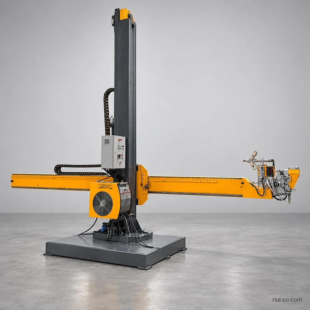
Automated lines need controllable and repeatable workpiece movement. The positioner can operate within a welding cell alongside a robot, column-and-boom manipulator or other controls when integration is designed into the project.
Better Access to Welds
Welds on the underside or far side of a large structure can otherwise force awkward or elevated working positions. Rotating the workpiece moves the joint into a more accessible location instead of forcing the operator to move around it.
Less Repeated Crane Handling
A crane remains necessary to load and unload heavy parts, but repeated crane lifts solely to change the welding angle consume time and occupy shared handling equipment. Once loaded, the positioner can perform many of those adjustments.
Safer, Less Fatiguing Work
Securing a heavy part to a purpose-designed rotating system can reduce reliance on temporary chains, hooks and manual repositioning. Proper design, capacity calculations, safe fixtures, training and operating procedures remain essential. Better working height and angle can also reduce bending, reaching and fatigue over a long shift.
More Consistent Welding and Production
A suitable position can make weld-pool control, torch distance, angle and travel speed easier to maintain. Controlled rotation supports repeatable conditions, although the positioner alone does not guarantee weld quality. Less time spent clamping, repositioning and waiting for a crane may improve the full production cycle.
Potential Indirect Savings
Possible savings include fewer lifts, shorter setup between welds, less crane occupation, fewer temporary fixtures, less rework from poor positioning and better use of labor and existing equipment. Actual savings should be calculated from part counts, current cycle times, handling frequency and labor costs.
Comparison with Common Positioner Designs
Single-Column Versus Two-Head Positioners
Criterion | Single-column positioner | Headstock-tailstock positioner |
|---|---|---|
Workpiece support | Mainly from one side | Supported at both ends |
Typical parts | Short, compact parts | Long parts, frames and large structures |
Plate loading | Long parts can create larger moments | Load shared between two heads |
Length adjustment | Usually not applicable | Head spacing can change |
Rotation | Depends on size and center of gravity | Around longitudinal axis between columns |
Long fixture mounting | More limited | Better suited |
Applications | Small and medium parts | Chassis, frames, booms and long structures |
A single-column unit is not inherently inferior; each layout suits different workpieces and loading conditions.
Fixed-Height Versus Height-Adjustable Designs
Feature | Fixed-height two-head | Height-adjustable two-head |
|---|---|---|
Rotation-axis height | Fixed | Adjustable |
Loading different parts | May need fixture changes | More flexible |
Operator access | Limited to chosen height | Can suit the operation |
Coordination with nearby equipment | Less flexible | Better for varied lines |
Initial cost | Usually lower | Reflects added complexity |
Best suited to | Repeated similar products | Varied parts and processes |
Height adjustment can improve access and ergonomics, especially where product sizes and adjacent equipment vary.
RSA Headstock-Tailstock Design Advantages
Designed Around the Customer’s Part
Weight, length, center of gravity, fixture, shop space and production process guide the machine design instead of forcing the line to fit a standard model.
Synchronized Height and Flexible Spacing
Coordinated lifting keeps the two heads aligned while changing the rotation-axis height. Adjustable spacing broadens the range of part lengths handled by one machine.
T-Slotted Plates and Independent Heads
T-slotted plates support direct mounting or dedicated fixtures. Where designed for it, each head can also perform suitable tasks independently.
Domestic Engineering Support
Local design and manufacture facilitate contact with the engineering team, fixture changes, production-line modifications, spare parts and technical service.
Technical Specifications
Specifications are determined for each order. No single load rating should be assumed for every project.
Specification | Configuration |
|---|---|
Load capacity | Designed for workpiece and fixture weight and center of gravity |
Distance between heads | Adjustable for the part-length range |
Height adjustment | Defined by project needs |
Rotation speed | Adjustable |
Plate diameter | Designed for the project |
Plate type | T-slotted |
Fixture | Standard or dedicated |
Control system | Matches required automation level |
Independent head use | Can be included in the design |
Remote control | Available to order |
Robot or column-and-boom integration | Can be assessed and designed |
Industrial finish | Matches site environment |
Safety equipment | Based on risk assessment and final design |
Confirm the final model datasheet before assigning numerical ratings.
When Is a Two-Head Positioner a Good Choice?
The part is too long to support comfortably from one side
Several faces require welding
Repeated crane repositioning consumes time
Operators struggle to access a joint
Products of different lengths share one line
Part and fixture weight rule out manual handling
Controlled, uniform rotation is required
Automated or robotic welding is planned
Repeatable part positions matter
Reducing non-welding cycle time is a project goal
For short, light or low-volume parts, a simpler positioner may be more economical. The decision should follow a review of cycle time, weight, geometry and expected use.
Points to Check Before Buying
Look Beyond Weight
Two workpieces with the same mass may impose very different torque and bearing loads because of differences in length, center of gravity and eccentricity. Include the weight of fixtures, clamps and accessories in capacity calculations.
Check Rotational Clearance
Calculate the maximum swept radius of the part and attachments so they cannot strike the floor, columns or nearby equipment.
Specify the Right Speeds
Positioning speed and welding travel speed may differ. Process, rotational diameter and cycle time determine the useful speed range.
Plan Loading and Controls
Overhead cranes, forklifts or other loading methods affect initial height and access. Specify local controls, pendant, foot pedal, wireless controls or production-line PLC integration at the design stage.
Design the Fixture with the Machine
A safe, accurate fixture is essential to positioner performance. Its attachment points and workpiece supports should be developed alongside the machine.
Ordering and Manufacturing Process
Receive the part drawing or 3D model, dimensions, weight and center of gravity
Review welding or assembly steps, production quantity, cycle time, loading method and operator needs
Calculate structure, torque, height range, head spacing, drive and fixture
Review the proposed layout, overall dimensions, workpiece mounting and controls with the customer
Build and machine the structure, assemble the mechanics and install controls after design approval
Test head movement, rotation, speed control, alignment, fixture and safety systems
Install and commission the machine and train operators in use and maintenance
Why RSA?
With more than two decades of industrial-equipment experience, RSA designs positioners around real production-line needs. Its work includes custom capacities and dimensions, industrial projects, suitable structural components, dedicated fixtures, integration with other line equipment, pre- and after-sales support, future modifications and direct contact with the design team.
The objective is a positioning solution that simplifies handling and supports safer, more consistent and more efficient production.
Frequently Asked Questions
How does it differ from a standard positioner?
Many standard positioners hold a part from one side or use a rotary and tilting table. A two-head system supports both ends and is better suited to long frames, chassis and similar structures.
Can the distance between heads change?
Yes. The longitudinal spacing can be designed to cover the specified workpiece-length range.
Do both sides adjust height together?
Yes. Coordinated adjustment is a core feature and helps maintain alignment.
Can each head be used on its own?
Independent operation can be included for suitable duties and capacities when specified at the ordering stage.
Is rotation speed adjustable?
Yes. The final speed range is specified from workpiece weight and dimensions and the welding process.
Which workpieces fit?
With suitable fixtures, chassis, frames, booms, box structures, machine components, rail equipment and other long or large parts can be mounted.
Can it work in a robotic welding cell?
Yes, if motion control, positioning accuracy, interfaces and safety requirements are included in the design from the start.
What is its load capacity?
There is no universal rating. Capacity depends on part and fixture weight, length, center of gravity, eccentricity and required rotation torque.
What determines the quoted price?
Capacity, supported length, height travel, plate dimensions, drive, controls, fixture, automation and safety equipment determine the final configuration and quotation.
What information is needed for a technical proposal?
Provide drawings or a 3D model, weight, minimum and maximum length, center of gravity, speed, loading method, production volume and process details.
Summary
A headstock-tailstock welding positioner supports, rotates and positions large or long parts for welding and assembly. Two-sided support, coordinated height adjustment, variable head spacing, controlled rotation and T-slotted plates provide flexibility across different production lines.
It can reduce repeated lifting, crane delays and work in awkward positions, creating better conditions for safety, weld consistency and throughput. RSA designs each unit around the customer’s workpiece weight, length, geometry, center of gravity and production process. Share the workpiece drawings, fixture weight and line requirements to request a technical proposal.
Comments (0)
No comments yet.
Leave a comment
Comments and replies appear after moderator review.