
Industrial equipment
Railway Wheel Tyre Press Machine
A railway wheel tyre press is designed for controlled installation and removal of a steel tyre on a rail wheel centre. A hydraulic system, rigid frame and dedicated fixtures apply force evenly while maintaining alignment.
Talk to an engineerFull description
A railway wheel tyre press is a specialist hydraulic machine for controlled installation, seating and removal of a steel tyre on a railway wheel centre. It is intended for rail-industry workshops, locomotive repair facilities and fleet-maintenance centres.
Some railway wheels use a separate wear-resistant steel ring rather than a one-piece wheel. This ring, called a tyre, forms the running surface and can be replaced when worn. It is generally fitted to the wheel centre by an interference or shrink fit: the tyre bore is slightly smaller than the outside of the centre at the specified reference condition.
The press applies controlled force while supporting and aligning the parts. Frame, hydraulic force, fixtures, control system and automation can be designed around the wheel dimensions and approved maintenance procedure.
What Is a Railway Wheel Tyre?
A tyre is a thick steel ring fitted around the centre of certain locomotive, wagon and specialist rail wheels. It includes the tread and guiding flange that contact the rail. Replacing the ring, rather than the whole wheel centre, can restore a worn running surface on equipment designed for this construction.
A tyred wheel may include the centre, tyre, tread, flange, retaining groove or other securing feature and, where specified, a retaining ring. The tyre must be seated concentrically and securely. Poor installation can lead to looseness, stress concentrations, out-of-roundness or safety problems.
What Does the Tyre Press Do?
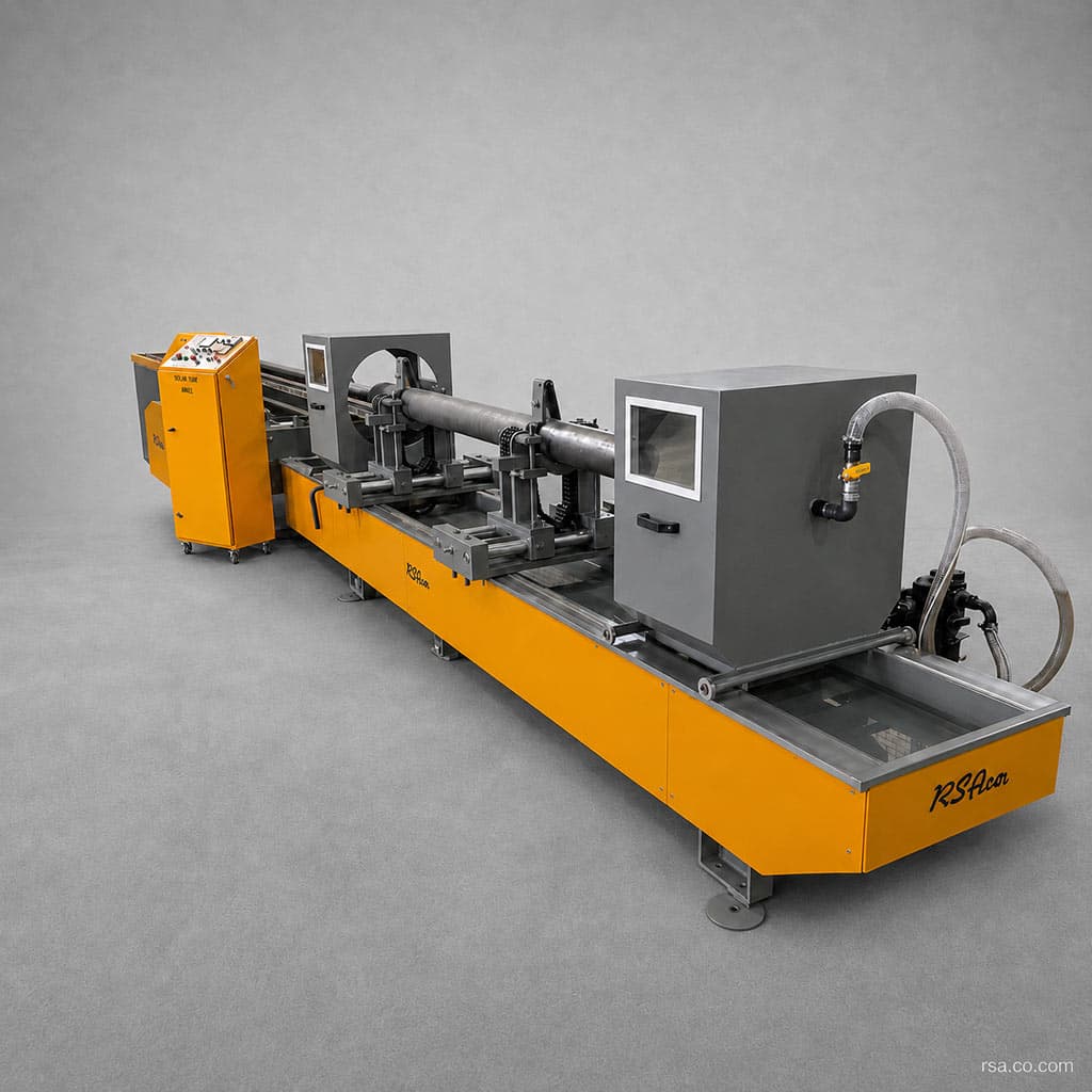
The hydraulic press applies substantial controlled force to the tyre, wheel centre or installation and removal tools. A typical arrangement includes a heavy frame, one or more hydraulic cylinders, a moving ram, workpiece supports, dedicated fixtures and controls.
Depending on the approved process, the machine can be designed to fit a tyre, set its final position, remove a worn tyre, fit or remove a retaining ring, apply a post-assembly test force, check position relative to the wheel centre, or assemble similar heavy rings.
Tyred Wheel Versus Monobloc Wheel
A monobloc wheel has the centre, tread and flange formed from one steel piece. A tyred wheel has a separate wheel centre and outer ring.
Feature | Tyred wheel | Monobloc wheel |
|---|---|---|
Structure | Separate centre and outer ring | Single integral wheel |
Wear component | Replaceable tyre | Part of the wheel itself |
Repair | Tyre can be replaced | Usually reprofiling or wheel replacement |
Assembly | Shrink or interference fit | No tyre assembly |
Equipment | Tyre heater and press | Wheel-to-axle assembly equipment |
Inspection | Tyre-to-centre joint must be checked | Focus on integral wheel condition |
Monobloc wheels are common in newer fleets, while tyred wheels remain in some locomotives and specialist equipment. The applicable rail requirements for each construction must be followed.
How the Railway Wheel Tyre Press Works
The exact method depends on wheel design and the approved maintenance procedure. A typical installation sequence is:
1. Prepare the Tyre and Wheel Centre
Check dimensions, material and condition. Contact surfaces must be clean and free of unacceptable rust, contamination or damage. Verify tyre bore and wheel-centre outside diameter against the drawings and tolerances.
2. Heat the Tyre
For a shrink fit, heat expands the tyre bore temporarily. Heating temperature, hold time and temperature uniformity must follow the technical procedure; uneven heating can distort the ring or introduce unwanted stress.
3. Position the Wheel Centre
Place the centre on machine supports or fixtures and align its axis with the press stroke. The fixture prevents sideways movement or tilting.
4. Present the Heated Tyre
Use suitable handling equipment to position the heated tyre around the centre. Timing matters because the ring starts cooling and contracting after leaving the heater.
5. Apply Controlled Force
Move the ram at the specified speed to guide the tyre into position. Distribute force evenly to avoid cocking. Cylinder capacity and hydraulic pressure are chosen from wheel dimensions, fit interference and the approved assembly method.
6. Check Final Position
Check the tyre against shoulders, seats and grooves. Install any retaining ring or other securing part required by the wheel design.
7. Cool the Assembly
As it cools, the tyre contracts onto the wheel centre. Cooling must follow the approved procedure.
8. Perform Final Inspection
Check tyre position, concentricity, looseness, final dimensions, surface condition and any retaining ring. Additional tests or a proof force may be required by the approved procedure.
Removing a Worn Tyre
With suitable fixtures, the press can hold the wheel centre and apply force to separate an old tyre. The sequence may involve removing the retaining ring, controlled tyre heating, supporting the centre, progressively pressing off the ring and inspecting the seat afterward. Asymmetric force or inappropriate tooling can damage the centre.
Main Machine Components
Frame
The frame must withstand pressing loads without excessive deformation. Plate thickness, joints and foundation anchoring are established by engineering calculations; excessive deflection can reduce accuracy and alignment.
Hydraulic Cylinders
Cylinder bore, stroke, pressure and mounting depend on the required force and wheel dimensions. The design may use one central cylinder or several synchronized cylinders.
Hydraulic Power Unit
The power unit may include a reservoir, pump, electric motor, directional and pressure-control valves, filters, heat exchanger, gauges, pipes and fittings. It controls approach speed, pressing force and ram return.
Ram and Moving Platen
The ram transfers cylinder force to the part or press tooling. It must distribute the load with adequate structural strength.
Wheel-Holding Fixture
The fixture locates the wheel centre and tyre without harmful point loads. Replaceable fixtures allow more than one wheel type to be handled.
Installation and Removal Tooling
Pressure rings, support plates, guide bushings and dedicated holders transfer force according to tyre and wheel-centre geometry.
Force and Position Measurement
A load cell or calibrated pressure sensor can measure force; a digital scale or displacement sensor can record ram position. Together, these data support process analysis, overload prevention and quality records.
Electrical Controls
The cabinet controls the motor, hydraulic valves, sensors and safety equipment. The project may specify manual or relay controls, a PLC and an HMI.
Safety Equipment
Depending on risk assessment, provisions may include emergency stop, guarded press area, light curtain, guard interlocks, pressure limiting, travel limits, audible and visual alarms, two-hand control, prevention of unintended ram movement and safe pressure release.
Benefits of a Dedicated Tyre Press
Controlled force along a defined axis can reduce tyre tilting and damage to the wheel seat. Accurate fixtures improve concentricity, while guards and controls reduce risks associated with handling hot, heavy parts. Force, speed and final position can be repeated for similar wheels. On equipped models, force, displacement, cycle time and outcome may be recorded. Replaceable tooling can accommodate several wheel designs and reduce turnaround time.
Force and Displacement Monitoring
A force-versus-displacement curve plots press load against ram travel. It can reveal abnormal load increases, a tyre sticking or tilting, premature stops, force outside an approved band, differences between cycles and possible dimensional errors. Acceptance limits must be defined from engineering drawings, actual tolerances and an approved process, not inferred from the graph alone.
Technical Specification Framework
Because wheel types vary, final capacity and dimensions are set only after reviewing the workpiece. The following are configurable fields, not fixed performance claims:
Specification | Configuration |
|---|---|
Machine | Railway wheel tyre press |
Actuation | Hydraulic |
Application | Tyre installation and removal |
Rated press force | Defined for the order |
Maximum stroke | Matches the workpiece |
Wheel-diameter range | Customizable |
Maximum workpiece weight | Matches the design |
Cylinder count | According to design |
Approach speed | Adjustable |
Pressing speed | Adjustable |
Pressure control | Adjustable |
Force measurement | Available |
Displacement measurement | Available |
Control system | Manual, PLC or HMI |
Curve recording | Custom option |
Fixtures | Matched to wheel types |
Loading | Crane or dedicated system |
Safety equipment | Based on risk assessment |
Electrical supply | Specified in the order |
Actual press force, stroke, supported diameter and speed should be published only after wheel and process data have been reviewed.
Custom Configuration Options
Project-specific force and wheel-diameter range
Interchangeable fixtures and installation/removal tools
Retaining-ring installation equipment
Manual or automatic controls with PLC and touchscreen
Programs for different wheel types
Force–displacement graphs and workpiece records
Printed process reports
Loading and unloading systems or transfer tables
Separate rapid-approach and working speeds
Two-hand controls, light curtains and guards
Oil cooling, plant-network connection and fault diagnostics
Why Fixture Design Matters
Adequate frame and hydraulic capacity cannot compensate for an unsuitable fixture. It must center the part, transfer force to the correct surface, support its weight, protect sensitive areas, allow safe loading and fast changeover, prevent unintended movement and permit inspection of tyre position. Modular tooling can serve several wheel models.
Quality Control After Installation
Inspect the wheel assembly against the project’s approved requirements. Possible checks include tyre position and concentricity, final diameter, shoulder clearance, retaining-ring condition, surfaces and possible cracks, looseness, runout and profile dimensions. If specified, perform acoustic or impact checks. Record wheel and tyre serial numbers, press-force data and final quality approval. Tests and limits must come from valid drawings, standards or maintenance instructions.
Choosing a Tyre Press
Actual Press Capacity
Size force capacity from the maximum required operation and an appropriate design margin, rather than an approximate number that could under- or oversize the machine.
Wheel Diameter, Width and Weight
Wheel dimensions determine machine opening, cylinder stroke, ram and fixture size. Weight determines supports and loading equipment.
Operations and Wheel Models
Specify whether the machine only installs tyres or also removes them, handles retaining rings and performs post-assembly tests. If several wheel types are involved, define their full dimensional range and fixture-change method.
Throughput and Heating
Parts per shift affect press speed, power-unit duty, cooling and automation. If tyre heating is part of the line, assess transfer time from heater to press because the ring cools before installation.
Traceability and Operator Safety
For traceable work, specify part identity, force, time and cycle-result logging. Heavy components, hot tyres and high forces require a complete risk assessment.
Installation and Commissioning
Check floor capacity, foundation, surrounding space, workpiece routes, crane access, power-unit location, maintenance access, electrical supply, ventilation, lighting, safe operator access, tyre-heater location, fire protection and emergency egress. After installation, level and anchor the machine and complete no-load, functional and loaded tests before training operators.
Maintenance
Preventive maintenance should cover hydraulic oil level and cleanliness, filter changes, cylinder and hose leaks, system pressure, frame bolts, fixtures and tooling wear, sensor cleaning, load-cell calibration, position sensing, emergency stop, light curtains and interlocks, relief valves, power-unit temperature, PLC backups and repair records. Set service intervals from operating hours, cycle count and environment.
Information Needed for a Custom Order
Provide tyre and wheel-centre drawings, inside and outside tyre diameters, centre diameter, tyre width, part weights, fit interference, installation temperature, required force and stroke, installation and removal methods, retaining-ring type, number of wheel models, daily or shift throughput, loading method, automation and reporting needs, and applicable standards or repair procedures. These inputs guide frame, hydraulic, fixture, tooling and control design.
Summary
A railway wheel tyre press is a specialist machine for controlled installation and removal of a steel tyre on a railway wheel centre. Its hydraulic system, rigid frame and dedicated fixtures distribute force while maintaining alignment.
Force and displacement measurement can support process records and inspection. Because wheel construction, fit, dimensions and weight differ, press force, travel, fixtures, loading and automation must be engineered from the actual wheel and approved procedure.
Comments (0)
No comments yet.
Leave a comment
Comments and replies appear after moderator review.